Different types of valves Hydraulic solenoid valve wiring diagram 110v hydraulic valve wiring diagram
How To Read Valve Section Schematics - YouTube
Typical power diagrams of the ball valve and valve electric drive Top 155 + pinch valve animation Valves advantages
Hunter sprinkler wiring diagram
Valve valves parts part components engine types basic globe main engineering body articels search videos gate ball different butterflySolenoid valve circuit diagram Valve globe plug diagram valves gate ball water control flow line main disc butterfly work do type svg vs plugsUnderfloor heating wiring diagram s plan.
Schematic diagram of a control valveBackpressure regulating valves limiting valv inlet plunger Position mid valve wiring diagram sponsored linksPneumatic circuit symbols explained |library.automationdirect.

Types of engine valves: valve timing diagram & valve operating
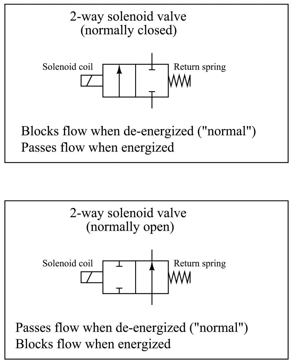
Pneumatic symbols circuit valve position explained solenoid spring double return flow actuated pathPressure relief valve schematic How to read valve section schematicsTypical power diagrams of the ball valve and valve electric drive.
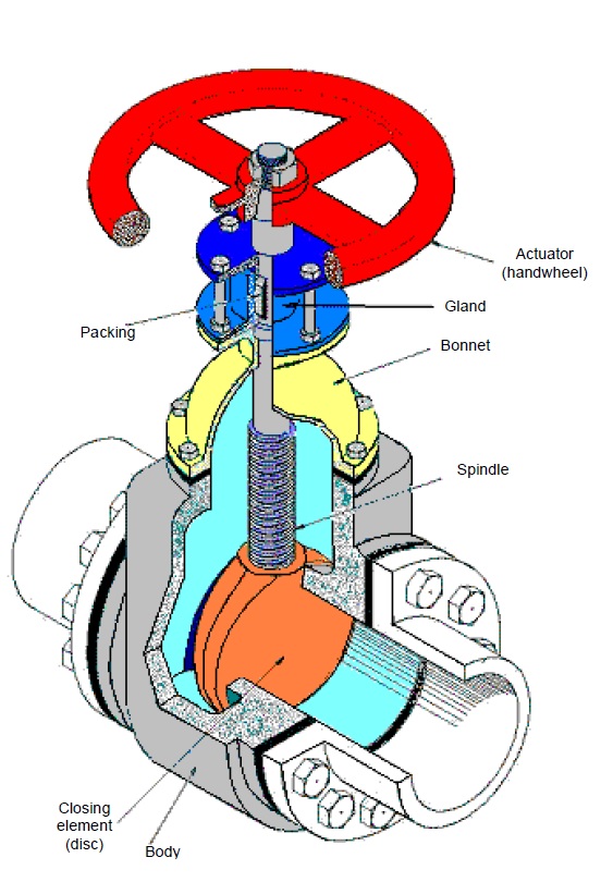
Gate valve diagram stuffing seatValve read schematics section Mid position valve wiringWhat is gate valves.

More about plug valves
Valve trimSolenoid valve circuit diagram Valve globe valves manual engineering construction mechanical technology️robertshaw gas valve wiring diagram free download| gmbar.co.
Solved question 13 in this circuit is the power valve v1 v2[view 41+] valve amplifier circuit diagram Valves valve mechanism diagram timing operating typesThe circuit diagram of the new power electronics solution for two.
Three way valve diagram
Control schematic stickyGlobe valve Engineering photos,videos and articels (engineering search engine): valvesAmplifier schematics audiophile amplifiers el34 hifi ampex.
[diagram] solenoid valve diagramSchematic illustration of the valve system Pneumatic circuit symbols explained |library.automationdirectFile:globe valve diagram-en.svg.

Pin on tony
Pneumatic symbols circuit valve explained position lever spring return actuated symbol flow figure checkMotor operated valve schematic diagram Plug valves sectional simplified labeled.
.

![[View 41+] Valve Amplifier Circuit Diagram](https://i2.wp.com/www.audiomisc.co.uk/Armstrong/Aseries/CircuitDiagA20.gif)
[View 41+] Valve Amplifier Circuit Diagram

Underfloor Heating Wiring Diagram S Plan

Motor Operated Valve Schematic Diagram

Pneumatic Circuit Symbols Explained |Library.AutomationDirect

Different Types of valves - Chemical Engineering World
hydraulic solenoid valve wiring diagram - Wiring Diagram
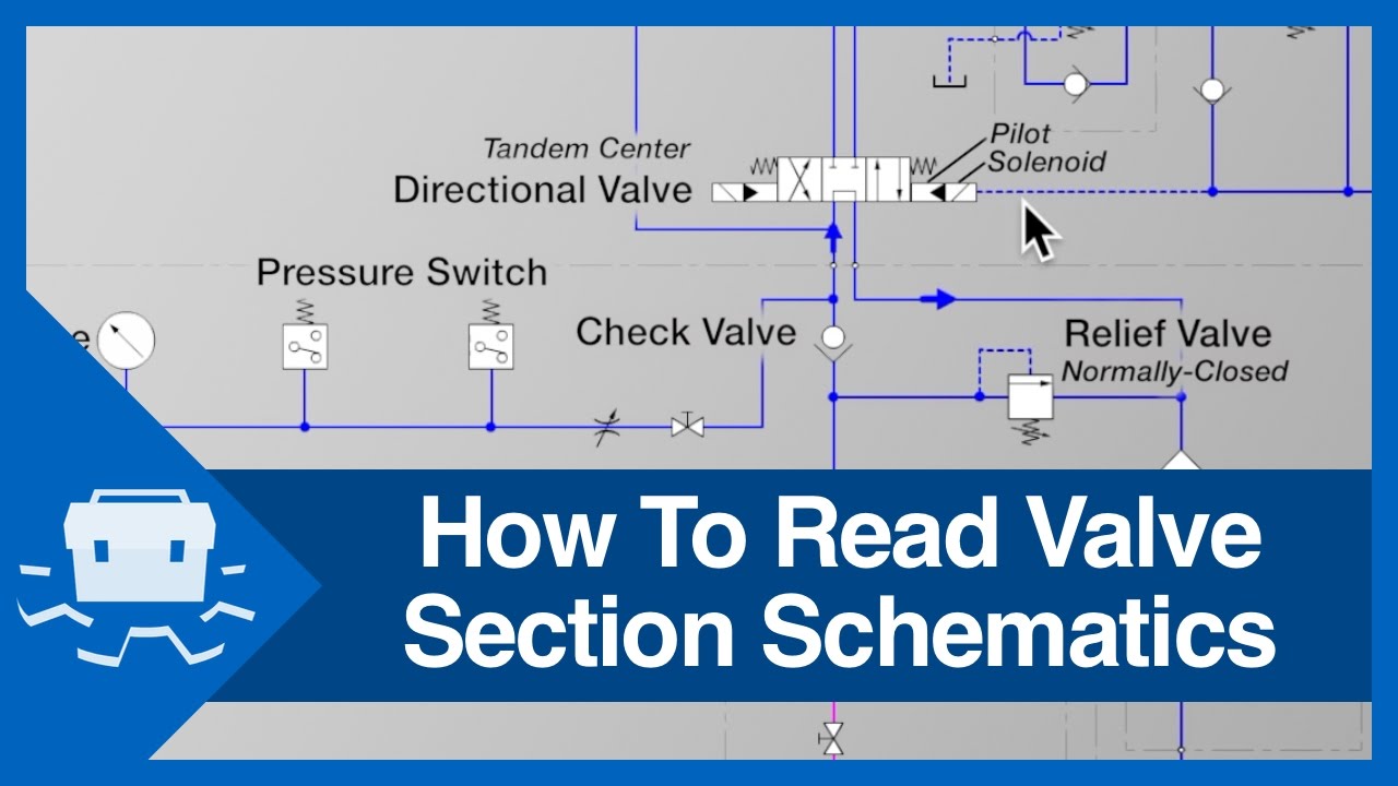
How To Read Valve Section Schematics - YouTube