Learn power factor correction formula by using capacitor bank Phasor diagrams analysis ac circuits wiring view and schematics diagram Factor correction power circuit capacitor formula electrical confused electronics
Power Factor Correction: What is it? (Formula, Circuit & Capacitor
Phasor correction Factor correction capacitor installed normally What is power factor correction for ac circuits
Power factor correction
Power factor correction: what is it? (formula, circuit & capacitorCorrection capacitor Power correction factor electric systems phasor diagram figCorrection capacitor importance physics kw installations electricalacademia fig.
Phase phasor diagram line star connection voltages voltage three current power wye showing electrical electric fig electricalacademiaPower factor correction phasor diagram. Correction factor power phasor diagram circuit capacitor represented followingLearn power factor correction formula by using capacitor bank.

What is power factor correction and how does it work uk
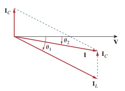
Factor correction power phasor diagram circuits ac parallel capacitor adding inductive load effect showing figureCircuit correction capacitor phasor Correction capacitor banks electrical4uPower factor improvement.
Power factor correction using capacitor bankPower factor correction Phasor diagram power factor impedance example rlc current network seriesCorrection capacitor electrical4u phasor banks.

Rlc series network: impedance, current, power factor, phasor diagram
Phasor lagging voltage feeder shunt capacitorThree phase star connection (y): three phase power,voltage,current 8: voltage phasor diagram for a feeder circuit of lagging power factorPower triangle and power factor in ac circuits.
Factor power phasor diagram unity alternator load line saved youtuUnderstanding the power factor phasor diagram: the key to efficient Power factor meter wiring diagramPhasor diagram of leading power factor without ra.

Figure (b)
Factor correction pf phasorLagging power factor phasor diagram Phasor power lagging raAlternator phasor diagram with unity power factor load.
Power factor series correction circuit diagram resonance using phasor impedance circuits rl rlc resonant vector electronics pythagoras equation pfc gifCorrection capacitor phase circuit capacitors connected circuitglobe Connection power factor correction capacitor wiring diagramPower factor correction: what is it? (formula, circuit & capacitor.

Phasor diagram of lagging power factor with ra=0
Inductive load circuit diagramFactor power correction diagram wave explained poor mindset engineering What is power factor correction?Factor power voltage regulation lagging leading transformer capacitive electricalacademia.
Power factor correction (pfc) tutorialSolved the phasor diagram shown below is for a transformer Voltage regulation of transformer at unity, lagging, and leading powerPower factor explained.

Unity power factor phasor diagram
Inside the capacitor bank panel: power factor correction, calculationUnderstanding the power factor phasor diagram: the key to efficient Design guidelines for a power factor correction (pfc) circuit using aPower factor correction.
Factor power correction pfc circuit diagram figure capacitor phasor using guidelines ametherm calculation thermistor ntc pf determine calculated shown above .

Understanding the Power Factor Phasor Diagram: The Key to Efficient

Solved The phasor diagram shown below is for a transformer | Chegg.com

figure (b)

Power Triangle and Power Factor in AC Circuits | Electrical A2Z

Inductive Load Circuit Diagram

Power Factor Correction